What is a hydraulic pump?
It seems like such a basic question to ask, but unfortunately, many who even work in this industry do not know the function of a hydraulic pump. When I was first taught about the function of a hydraulic pump, I was told its only job was to provide flow. I was also told that any pressure in a hydraulic system was a result of resistance to that flow. However, these claims are both wrong. So, what is a hydraulic pump?
Hydraulic pumps are used in hydraulic drive systems and can be hydrostatic or hydrodynamic. A hydraulic pump is a mechanical source of power that converts mechanical power into hydraulic energy. It generates flow with enough power to overcome pressure induced by the load at the pump outlet.
A hydraulic pump converts the mechanical energy from the prime mover into hydraulic energy for use by the system. Hydraulic energy is the combination of pressure and flow required by the actuators to perform useful work. It is important to understand that hydraulic energy is both pressure and flow combined, because one without the other cannot achieve work. Pressure would just consist of trapped fluid and flow would have no energy to move fluid alone.
The mechanical device that is used to convert mechanical power into hydraulic energy is known as a hydraulic pump. The load that is responsible for the pressure is overcome with this device by creating sufficient power and generating a flow.
The hydraulic pump has two functions to perform during operation, allowing atmospheric pressure to push liquid into the inlet line from the reservoir to the pump by the mechanical action created vacuum at the pump. The other function it performs is that the pumps mechanical action supplies the liquid to the pump outlet and then forced into the hydraulic system.
A hydraulic pump pushes on fluid, and in this regard, fluid can be considered a solid as it is transmitted throughout the machine and then pushes on actuators to eventually move loads. Motion control professionals will have me point out that oil is compressible, but that’s a discussion for another blog. The point is that a pump could be pushing on sand, ball bearings or any other solid medium capable of taking the shape of its container, and the result would still be the transmission of force.
Transmission of force is really the name of the game with hydraulics, and is the basis for Cosford’s Law, which states that “pressure makes it go, flow is just the rate in which you can create pressure.” For fluid to be moving, pressure must absolutely be highest at the pump; always. This flies in the face of the fallacy that pressure is resistance to flow. Pressure will rise as high as it needs to be to overcome downstream resistance, but if it didn’t start at the pump, fluid would move backwards.
Pressure in hydraulics is the result of Newton’s Third Law of Motion, that every action has an equal and opposite reaction. The opposing force can be a loaded cylinder or a flow control, and the pump doesn’t care which. It will continue to push the fluid as pressure rises to overcome resistance, even if it results in something blowing up or the prime mover being overloaded.
Flow from a pump is a function of displacement (volume) and speed. A larger pump can push more fluid at once, or by spinning a pump faster, it will push on fluid more often. Just like in the world of electrons, where power is a combination of voltage and amperage, power in hydraulics is a combination of pressure and flow. By doubling pressure while leaving flow the same, horsepower is doubled. Also, by doubling flow while leaving pressure the same, horsepower is also doubled.
Understanding the operation of a hydraulic pump will do volumes (no pun intended) for your understanding of fluid power. When you realize all energy starts at the pump, you can better design or troubleshoot any system.
Types of hydraulic pumps
There are typically three types of hydraulic pump constructions found in mobile hydraulic applications. These include gear, piston and vane; however, there are also clutch pumps, dump pumps and pumps for refuse vehicles such as dry valve pumps and Muncie Power Products’ Live PakTM.
The hydraulic pump is the component of the hydraulic system that takes mechanical energy and converts it into fluid energy in the form of oil flow. This mechanical energy is taken from what is called the prime mover (a turning force) such as the power take-off or directly from the truck engine.
With each hydraulic pump, the pump will be of either a uni-rotational or bi-rotational design. As its name implies, a uni-rotational pump is designed to operate in one direction of shaft rotation. On the other hand, a bi-rotational pump has the ability to operate in either direction.
Gear pumps
For truck-mounted hydraulic systems, the most common design in use is the gear pump. This design is characterized as having fewer moving parts, being easy to service, more tolerant of contamination than other designs and relatively inexpensive. Gear pumps are fixed displacement, also called positive displacement, pumps. This means the same volume of flow is produced with each rotation of the pump’s shaft. Gear pumps are rated in terms of the pump’s maximum pressure rating, cubic inch displacement and maximum input speed limitation.
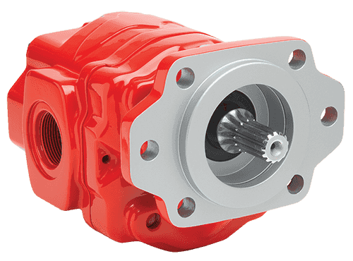
Generally, gear pumps are used in open center hydraulic systems. Gear pumps trap oil in the areas between the teeth of the pump’s two gears and the body of the pump, transport it around the circumference of the gear cavity and then force it through the outlet port as the gears mesh. Behind the brass alloy thrust plates, or wear plates, a small amount of pressurized oil pushes the plates tightly against the gear ends to improve pump efficiency.
- Most common design
- Fewer moving parts, easy to service, more tolerant of contaminates, relatively inexpensive
- Fixed, also called positive, displacement pumps
- Rated in terms of max pressure rating, cubic inch displacement, max input speed limitation
- Used in open center hydraulic systems
- Transports oil around circumference of gear cavity and forces it through outlet port
- Encompasses thrust plates that push against gear ends with small amount of pressurized oil to improve pump efficiency
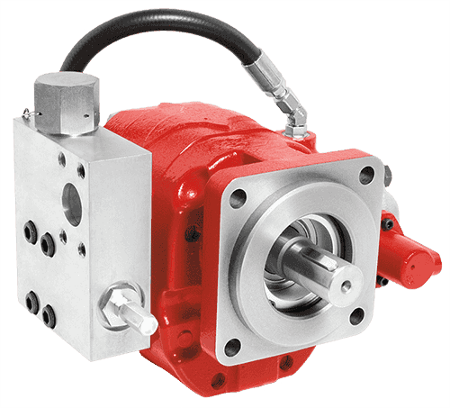
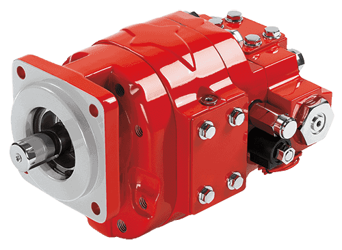
Piston pumps
When high operating pressures are required, piston pumps are often used. Piston pumps will traditionally withstand higher pressures than gear pumps with comparable displacements; however, there is a higher initial cost associated with piston pumps as well as a lower resistance to contamination and increased complexity. This complexity falls to the equipment designer and service technician to understand in order to ensure the piston pump is working correctly with its additional moving parts, stricter filtration requirements and closer tolerances. Piston pumps are often used with truck-mounted cranes, but are also found within other applications such as snow and ice control where it may be desirable to vary system flow without varying engine speed.
A cylinder block containing pistons that move in and out is housed within a piston pump. It’s the movement of these pistons that draw oil from the supply port and then force it through the outlet. The angle of the swash plate, which the slipper end of the piston rides against, determines the length of the piston’s stroke. While the swash plate remains stationary, the cylinder block, encompassing the pistons, rotates with the pump’s input shaft. The pump displacement is then determined by the total volume of the pump’s cylinders. Fixed and variable displacement designs are both available.
- Withstand higher pressures
- Higher initial cost, lower resistance to contamination and increased complexity
- Additional moving parts, stricter filtration requirements and closer tolerances
- Truck-mounted cranes
- Good when desirable to vary system flow without varying engine speed
- Fixed and variable displacement designs available
- Encompasses cylinder block containing pistons that move in and out – this movement draws oil from the supply port and forces through the outlet
- Angle of swash plate determines the length of the piston’s stroke
- Swash plate remains stationary
- Displacement determined by total volume of pump cylinders
Fixed displacement
With a fixed displacement piston pump, the swash plate is nonadjustable. Its proportional output flow to input shaft speed is like that of a gear pump and like a gear pump, the fixed displacement piston pump is used within open center hydraulic systems.
Variable displacement
As previously mentioned, piston pumps are also used within applications like snow and ice control where it may be desirable to vary system flow without varying engine speed. This is where the variable displacement piston pump comes into play – when the hydraulic flow requirements will vary based on operating conditions. Unlike the fixed displacement design, the swash plate is not fixed and its angle can be adjusted by a pressure signal from the directional valve via a compensator.
Should more flow be required, the swash plate angle changes, increasing the pump displacement by creating a longer piston stroke. Contrary to a fixed displacement piston pump, the variable displacement is used in a closed center system. With a closed center system, the swash plate angle within the variable displacement pump decreases as the flow requirement diminishes so that there is no excess flow or loss of hydraulic horsepower.
Variable displacement piston pumps can be flow compensated, pressure compensated or both flow and pressure compensated.
Flow Compensated – As flow requirements change, the swash plate angle is adjusted to maintain a constant margin of pressure.
Pressure Compensated – Regardless of changes in system pressure, a specified flow is maintained through adjusting the swash plate angle.
Flow and Pressure Compensated Combined – These systems with flow and pressure compensation combined are often called a load-sensing system, which is common for snow and ice control vehicles.
Vane pumps
Vane pumps were, at one time, commonly used on utility vehicles such as aerial buckets and ladders. Today, the vane pump is not commonly found on these mobile (truck-mounted) hydraulic systems as gear pumps are more widely accepted and available.
Within a vane pump, as the input shaft rotates it causes oil to be picked up between the vanes of the pump which is then transported to the pump’s outlet side. This is similar to how gear pumps work, but there is one set of vanes – versus a pair of gears – on a rotating cartridge in the pump housing. As the area between the vanes decreases on the outlet side and increases on the inlet side of the pump, oil is drawn in through the supply port and expelled through the outlet as the vane cartridge rotates due to the change in area.
- Used on utility vehicles, but not as common today with gear pumps more widely accepted and available
- Input shaft rotates, causing oil to be picked up between the vanes of the pump which is then transported to pump outlet side as area between vanes decreases on outlet side and increases on inlet side to draw oil through supply port and expel though outlet as vane cartridge rotates
Clutch pumps
A clutch pump is a small displacement gear pump equipped with a belt-driven, electromagnetic clutch, much like that found on a car’s air conditioner compressor. It is engaged when the operator turns on a switch inside the truck cab. Clutch pumps are frequently used where a transmission power take-off aperture is not provided or is not easily accessible. Common applications include aerial bucket trucks, wreckers and hay spikes. As a general rule clutch pumps cannot be used where pump output flows are in excess of 15 GPM as the engine drive belt is subject to slipping under higher loads.
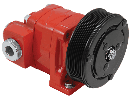
- Small displacement pumps
- Belt driven
- Aerial bucket trucks, wreckers and hay spikes
- Limited to 15 GPM applications
Dump pumps
Of the different types of hydraulic pumps, the dump pump is the most recognizable. This type of pump is commonly used in dumping applications from dump trailers to tandem axle dump trucks. The dump pump is specifically designed for one application – dump trucks – and is not suitable for other common trailer applications such as live floor and ejector trailers.
What separates this pump from the traditional gear pump is its built-in pressure relief assembly and an integral three-position, three-way directional control valve. The dump pump is unsuited for continuous-duty applications because of its narrow, internal paths and the subsequent likelihood of excessive heat generation.
Dump pumps are often direct mounted to the power take-off; however, it is vital that the direct-coupled pumps be rigidly supported with an installer-supplied bracket to the transmission case with the pump’s weight at 70 lbs. With a dump pump, either a two- or three-line installation must be selected (two-line and three-line refer to the number of hoses used to plumb the pump); however, a dump pump can easily be converted from a two- to three-line installation. This is accomplished by inserting an inexpensive sleeve into the pump’s inlet port and uncapping the return port.
Many dump bodies can function adequately with a two-line installation if not left operating too long in neutral. When left operating in neutral for too long however, the most common dump pump failure occurs due to high temperatures. To prevent this failure, a three-line installation can be selected – which also provides additional benefits.
- Dump pump most recognizable
- Specifically designed for dump trucks
- Displacement of slightly more than six cubic inches, pressure relief assembly and integral three-position, three-way directional control valve
- Not suited for continuous-duty applications
- Often direct coupled to PTO, need installer-supplied bracket to support
- Two- and three-line installations available (two-line can be converted to three-line)
Refuse pumps
Pumps for refuse equipment include both dry valve and Live Pak pumps. Both conserve fuel while in the OFF mode, but have the ability to provide full flow when work is required. While both have designs based on that of standard gear pumps, the dry valve and Like Pak pumps incorporate additional, special valving.
Dry valve pumps
Primarily used on refuse equipment, dry valve pumps are large displacement, front crankshaft-driven pumps. The dry valve pump encompasses a plunger-type valve in the pump inlet port. This special plunger-type valve restricts flow in the OFF mode and allows full flow in the ON mode. As a result, the horsepower draw is lowered, which saves fuel when the hydraulic system is not in use.
In the closed position, the dry valve allows just enough oil to pass through to maintain lubrication of the pump. This oil is then returned to the reservoir through a bleed valve and small return line. A bleed valve that is fully functioning is critical to the life of this type of pump, as pump failure induced by cavitation will result if the bleed valve becomes clogged by contaminates. Muncie Power Products also offer a butterfly-style dry valve, which eliminates the bleed valve requirement and allows for improved system efficiency.
It’s important to note that with the dry valve, wear plates and shaft seals differ from standard gear pumps. Trying to fit a standard gear pump to a dry valve likely will result in premature pump failure.
- Often used on refuse equipment
- Large displacement, front crankshaft-driven pumps
- Encompasses plunger-type valve in the pump inlet port restricting flow in OFF mode, but allows full flow in ON mode lowering horsepower draw to save fuel when not in use
- Fully functioning bleed valve critical to life of this pump
- Wear plates and shaft seals differ from standard gear pumps – trying to fit standard gear pump to dry valve likely will result in premature pump failure
LIVE PAKTM PUMPS
Live Pak pumps are also primarily used on refuse equipment and are engine crankshaft driven; however, the inlet on a Live Pak pump is not outfitted with a shut-off valve. With a Live Pak pump, the outlet incorporates a flow limiting valve. This is called a Live Pak valve. The valve acts as an unloading valve in OFF mode and a flow limiting valve in the ON mode. As a result, the hydraulic system speed is limited to keep within safe operating parameters.
- Primarily used on refuse equipment
- Engine crankshaft driven
- Inlet not outfitted with shut-off valve
- Outlet incorporates flow limiting valve called Live Pak valve – acts as an unloading valve in OFF mode and flow limiting valve in ON mode restricting hydraulic system speed to keep within safe operating parameters
Where are hydraulic pumps used?
Hydraulic pumps are an integral component of every hydraulic transmission system. It is the hydraulic pump that is tasked with converting mechanical energy into hydraulic energy. This process is facilitated by the pump inputting a force in a way that creates a flow of the hydraulic fluid. It is the pressure within the hydraulic fluid that facilitates the transfer from mechanical energy to hydraulic.
The most basic model of hydraulic pump is the hand pump. These are ideal for any situation that requires a low power application and a prime mover is either too expensive or unavailable. A hand pump can be used as a primary power source such as hydraulic power tools or a bench top hydraulic press. A hand pump can also be used as an auxiliary power source. This can include functions such as releasing hydraulic brakes on a tractor-trailer. The power input for a hand pump is low. Most humans can only input one-tenth of one horsepower for a maximum of a few seconds. Due to this low power, most hand pump applications are slow and can reach approximately 10,000 psi.
The typical hydraulic pump operates with an input powered by an internal combustion engine. Other pumps are powered an electric motor. Generally the combustion engine or electric motor input the mechanical energy into the hydraulic pump through a rotor or rotors. The mechanical energy will power the rotor, which will turn within the pump and transfer the mechanical energy to the hydraulic fluid. When the reciprocal force applied to the hydraulic liquid is high enough it will cause flow equal to the displacement volume of the pump. This process will also be affected by the rotational speed of the rotors.
There is a wide array of uses for hydraulic pumps such as the line from Enerpac. These pumps are installed in nearly every piece of mobile or industrial hydraulic machinery. Mobile machinery typically uses hydraulic pumps more frequently than industrial machinery. This is the case because mobile machinery rarely uses electric actuators. Hydraulic pumps are also frequently found on forestry equipment, mining machinery, excavators, dump trucks, cranes, graders, loaders, vacuum trucks, tractors and a host of other types of machinery.
It is still common to see hydraulic pumps in use in industrial environments. Generally speaking, hydraulic pumps are used more frequently in cases where the application is severe. Hydraulic pumps are most commonly found in steel mills, foundries, lifts, conveyors, injection molding machines, shear and stamping presses, mixers, forklifts, pallet jacks and more.