HYDRAULIC POWER UNITS
What are hydraulic power units (HPUs)?
Hydraulic power units (sometimes referred to as a hydraulic power pack) is a self-contained system that generally includes a motor, a fluid reservoir, and a pump. It works to apply the hydraulic pressure needed to drive motors, cylinders, and other complementary parts of a given hydraulic system.
A hydraulic system employs enclosed fluid to transfer energy from one source to another, and subsequently create rotary motion, linear motion, or force. The power unit/pack provide the power needed for this transfer of fluid.
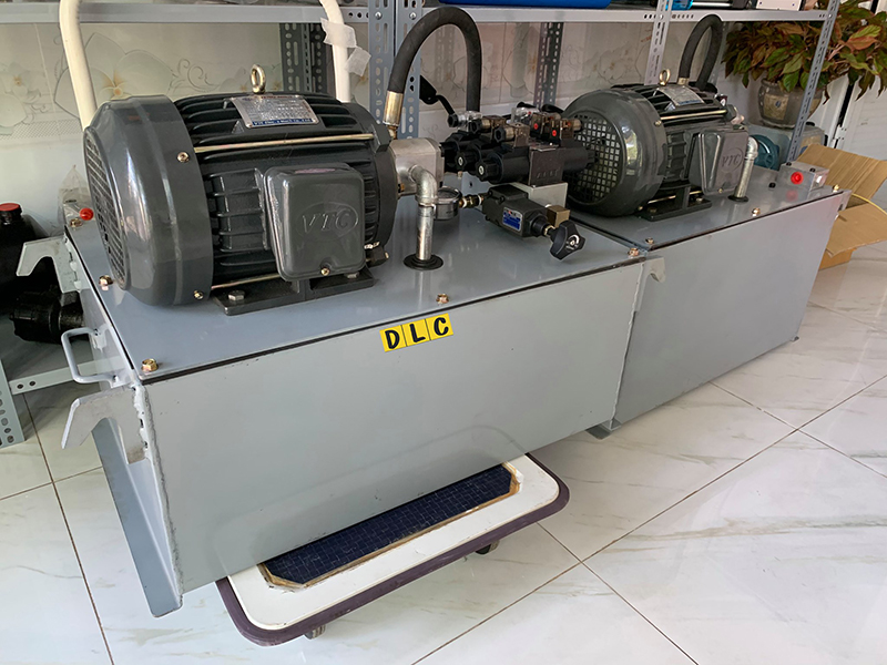
Unlike standard pumps, hydraulic power units use multi-stage pressurization networks to move fluid, and they often incorporate temperature control devices. The mechanical characteristics and specifications of a hydraulic power unit dictate the type of projects for which it can be effective.
Some of the important factors that influence a hydraulic power unit’s performance are pressure limits, power capacity, and reservoir volume. In addition, its physical characteristics, including size, power supply, and pumping strength are also significant considerations. To better understand the operating principles and design features in a hydraulic power unit, it may be helpful to look at the basic components of a standard model used in industrial hydraulic systems.
Hydraulic Power Pack/Unit Design Components
A large, durable hydraulic power unit built for functioning under a range of environmental conditions will have numerous design characteristics distinct from a typical pumping system. Some of the standard design features include:
Accumulators: These are containers that can be attached to the hydraulic actuators. They collect water from the pumping mechanism and are intended to build and maintain fluid pressure to supplement the motor pumping system.
Motor Pumps: A hydraulic power unit can be equipped with a single motor pump, or multiple devices each with their own accumulator valve. With a multiple pump system, usually only one operates at a time.
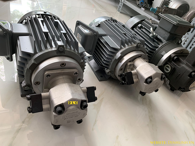
Tanks: The tank is a storage unit designed with enough volume for the fluid in the pipes to drain into it. Likewise, actuator fluid may sometimes need draining into the tank.
Filters: A filter is typically installed along the top of the tank. It is a self-contained bypass unit, with its own motor, pump, and filtering apparatus. It can be used to fill or empty the tank by activating a multi-directional valve. Because they are self-contained, filters can often be replaced while the power unit is functioning.
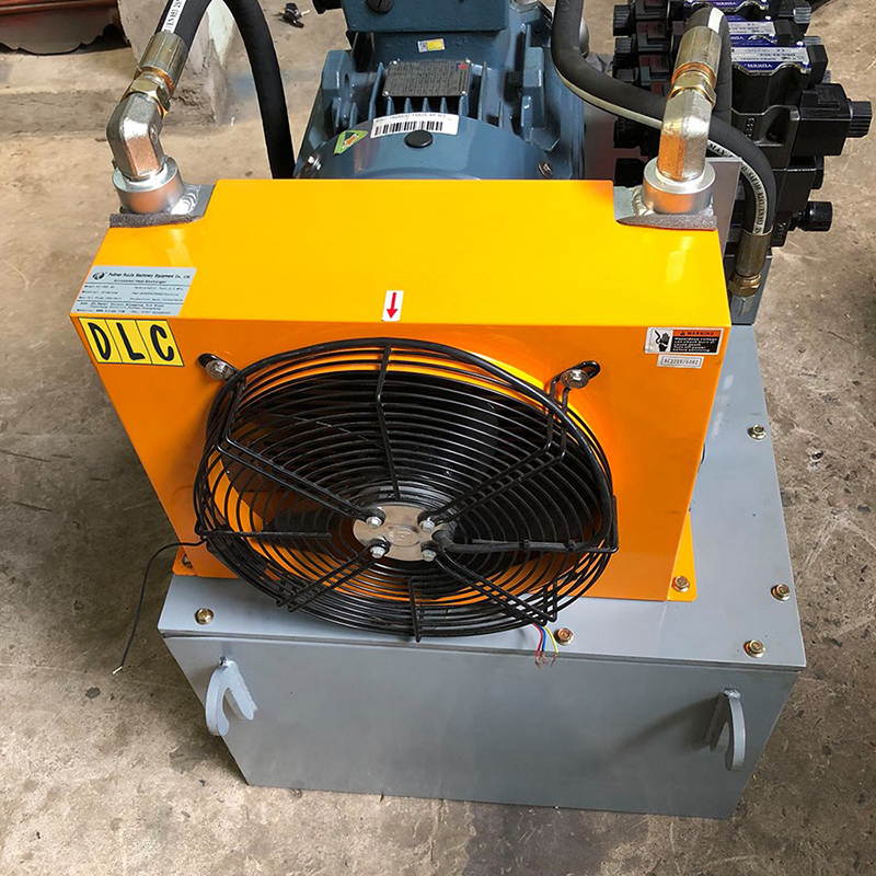
Coolers and Heaters: As part of the temperature regulation process, an air cooler can be installed near or behind the filter unit to prevent temperatures from rising above operational parameters. Likewise, a heating system, such as an oil-based heater, can be used to elevate temperatures when necessary.
Power Unit Controllers: The hydraulic controller unit is the operator interface containing power switches, displays, and monitoring features. It is necessary for installing and integrating a power unit into a hydraulic systems, and can usually be found wired into the power unit.
How do hydraulic power units work?
When a hydraulic power units begins functioning, the gear pump pulls hydraulic fluid out of the tank and moves it into an accumulator. This process continues until the pressure within the accumulator reaches a predetermined level, at which point a charging valve switches the pumping action to begin circulating fluid. This causes the pump to release fluid through a charging valve back into the tank at minimal pressure. A special one-way valve keeps fluid from flowing out of the accumulator, but if the pressure drops by a significant amount, the charging valve reactivates and the accumulator is refilled with fluid. Farther down the line, a reduced-pressure valve regulates the flow of oil moving to the actuators.
If the accumulator is equipped with a fast-stroking device, it can be connected to other accumulators to allow them to charge pressure as well. Often, an automatic thermostat or fan will be included to help alleviate rising temperatures. If the fluid in the system begins to overheat, a temperature switch can shut the motor-pump off, which can also help refill the tank if its fluid level is too low. If the hydraulic power unit has multiple motor pumps, a flow switch can have them alternate in case of reduced fluid supply. Pressure switches can be used to regulate accumulator pressure and a monitoring system can alert operators when pressure has dropped too low, elevating the risk of power unit failure.
What is the use of hydraulic power pack?
What components make up hydraulic power units or HPUs?
Nearly every single hydraulic system shares one thing in common — they’re run by a hydraulic power unit. Although some units are multitaskers, like the engine on a tractor, most often they’re purpose-built for the single task of converting mechanical energy into hydraulic energy. The scope of a power unit ranges from fractional horsepower electric units to monstrous constructions in the hundreds of horsepower.
The power unit exists to supply the machine with hydraulic energy in the form of pressure and flow, without which you have idle components. You must first calculate the pressure and flow required by the actuators in the systems (see sidebar on Pressure and flow requirements). You may calculate this step more than once as you balance performance with economy, as very few machinery OEMs have no limits, financial or otherwise
After you arrive at your pressure and flow requirements, you specify the pump type and size. Pump cost and complexity are vast but this dictates the level of performance you can expect to achieve with your actuators (see sidebar on Choosing a hydraulic pump). The type of pump used correlates with the direction you must take with reservoir design, filtration and complexity of pumping. A gear pump, for example, requires only suction and pressure lines. A load sensing piston pump, conversely, will add to that a case drain line and one or more hookups for the load sense network.
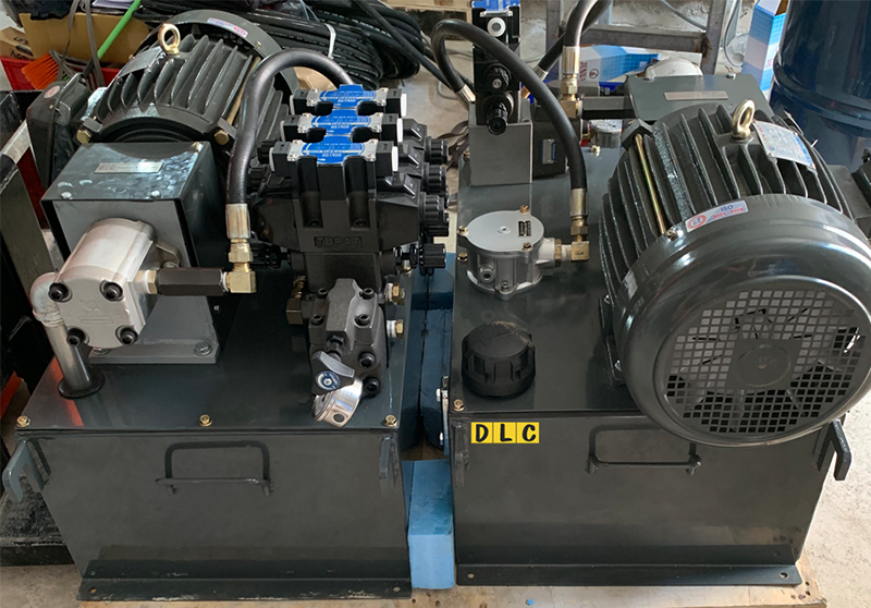
The pump now defined, the rest of the power unit can be built around it. You must now choose the size of your reservoir. Although opinions vary, you can’t go wrong with the advice to size it as large as possible. Limitations will exist for cost and footprint, but on average, expect to need at least three times pump flow at minimum, to ideally five times if it can be achieved. Every multiple of pump flow provides a precious extra minute of fluid dwell time. Reservoir size is critical for many reasons.
A large volume of hydraulic fluid relative to pump size gives time for fluid to cool before being drawn back into the circuit where heat soaks in once again. Large tank volume means large tank surface area, and in addition to the first point, this large surface provides a radiation layer to improve cooling. Additionally, with more fluid, particles settle more effectively than if they immediately re-enter the circuit, as with smaller tanks. Opposite to the settling of particles, air bubbles are given more time to rise, reducing the potential for cavitation-related damage from aeration.
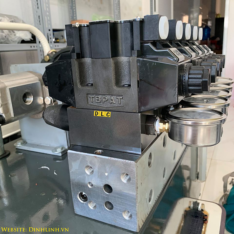
Highly complex hydraulic systems consist of many components—some related to the function of the circuits, like manifolds, directional valves and pressure valves—and other components required for fluid conditioning and monitoring. Filters, heat exchangers and pressure gauges are components added to ensure safe and reliable power unit operation. Because of ease and convenience, as many components as possible should mount to the reservoir. As such, these components command much real estate, and reservoirs are oversized to accommodate.
The most important set of components is the pump/motor assembly. It includes the chosen pump, a motor of adequate power capacity, a pump-motor mount and drive coupler set. The pump/motor mount — often called the bellhousing — rigidly fixes the C-Face electric motor to the pump and provides a gap to install the couplers. A coupler slides on the motor shaft, its mate slides on the pump shaft and then a synthetic rubber insert is placed between them before the couplers are pushed together and fixed in place with set screws. Be sure to select a coupler set rated for the required horsepower and pressure spike potential.
How to Select Hydraulic Power Motors
The power source, or prime mover, associated with most hydraulic power units is the motor, which is generally selected based on its speed, torque level, and power capacity. A motor whose size and capabilities complement those of the hydraulic power unit can minimize wasted energy and raise cost-efficiency in the long-term.
The criteria for motor selection vary according to the type of power source being employed. For example, an electric motor has an initial torque much greater than its operating torque, but diesel and gasoline-powered motors have a more even torque-to-speed curve, delivering a relatively steady amount of torque at both high and low running speeds. Consequently, an internal combustion engine may be able to initiate a loaded pump, but not provide enough power to bring it to operating speed if it is not properly matched with the hydraulic power unit.
Motor Size
As a rule of thumb, the power rating for a diesel or gasoline motor used with a hydraulic power unit needs to be at least double that of an electric motor suitable for the same system. However, the cost of the electricity consumed by an electric motor over its operational lifespan usually outstrips the cost of the motor itself, making it important to find an appropriately sized unit that will not waste energy consumption. If the pumping pressure and liquid flow are set at a constant rate, motor size can be measured according to the following parameters:
• Horsepower
• Gallons per minute
• Pressure, measured in pounds per square inch (psi)
• Mechanical pumping efficiency
In some cases, the hydraulic system may require different levels of pressure at various stages of the pumping process, meaning that horsepower can be calculated as the root mean square (rms) and a smaller motor may suffice for the project. However, the motor must still be able to meet the torque requirement for the highest pressure level in the cycle. Once the rms and the maximum torque (including initial and operational levels) have been calculated, they can be cross-referenced with a motor manufacturer’s performance charts to determine whether the motor is the necessary size.
Electric Motor Power
Electric motors and internal combustion motors, such as diesel or gasoline engines, exhibit different torque characteristics that dictate their varying power capacities. A typical three-phase electric motor begins its operating sequence by turning a rotor. When the rotor accelerates, the torque level drops slightly, then increases again when the rotation hits a specific rpm rate. This temporary drop is known as “pull-up torque,” while the maximum value is designated as “breakdown torque.” When the rotor speed surpasses the breakdown level, torque decreases steeply. An electric motor’s torque-to-speed curve remains roughly the same regardless of power capacity, and it is usually run at full-load speed but below the breakdown point to reduce any risk of stalling.
Gasoline and Diesel Motor Power
Internal combustion motors have a significantly different torque-to-speed curve with fewer torque fluctuations. Generally, diesel and gasoline motors have to operate at higher speeds to achieve the necessary torque to power a pump. A horsepower rating approximately two and a half times greater than that of an electric motor counterpart is typically required for an internal combustion engine to reach the torque levels needed for a hydraulic power unit. Manufacturers normally recommend that gasoline or diesel motors operate continuously at only a portion of their maximum rated power in order to prolong the motor’s lifespan, and keeping the torque below maximum level can often improve fuel efficiency.